Sean's Engineering Portfolio
- Todos + Current Issues (for quick personal reference)
- Overview
- Mechanical Parts
- Electronics
- Firmware
- Modeling and Dynamics
- \end{bmatrix}
- Inner Loop Motor Torque Control
Todos + Current Issues (for quick personal reference)
- Finish torque-based motor inner-loop control
- Need to fit data to a first-order model of motor output torque
- switch to Serial from MQTT for high-frequency data collection fidelity
- Characterize $t_{TC}$ for reaching torque target
- Characterize $I_{zz}$ of cubli using string suspended spin test
- Migrate state space realization into Simulink and intuitively verify system behaves as expected
- Sanity check the measurement model using real world experiment and validate $C$ with collected data
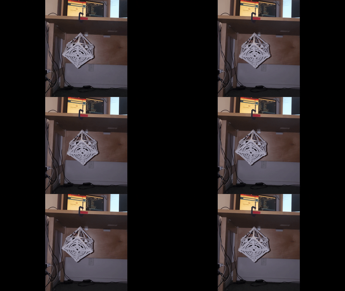
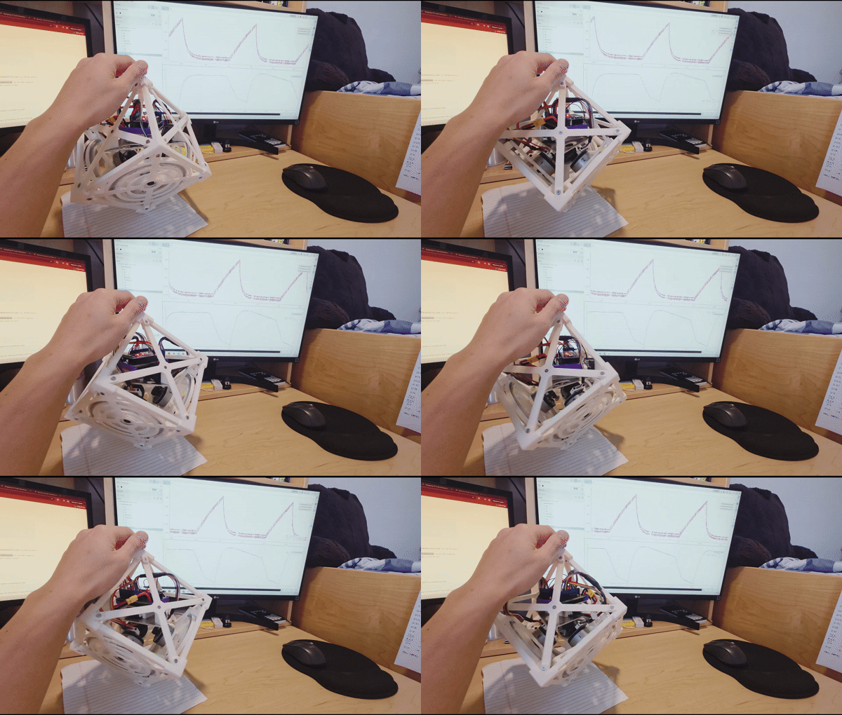
- Big live telemetry progress lately!
Overview
github: https://github.com/slin1923/cublii
updated 9/16/2026
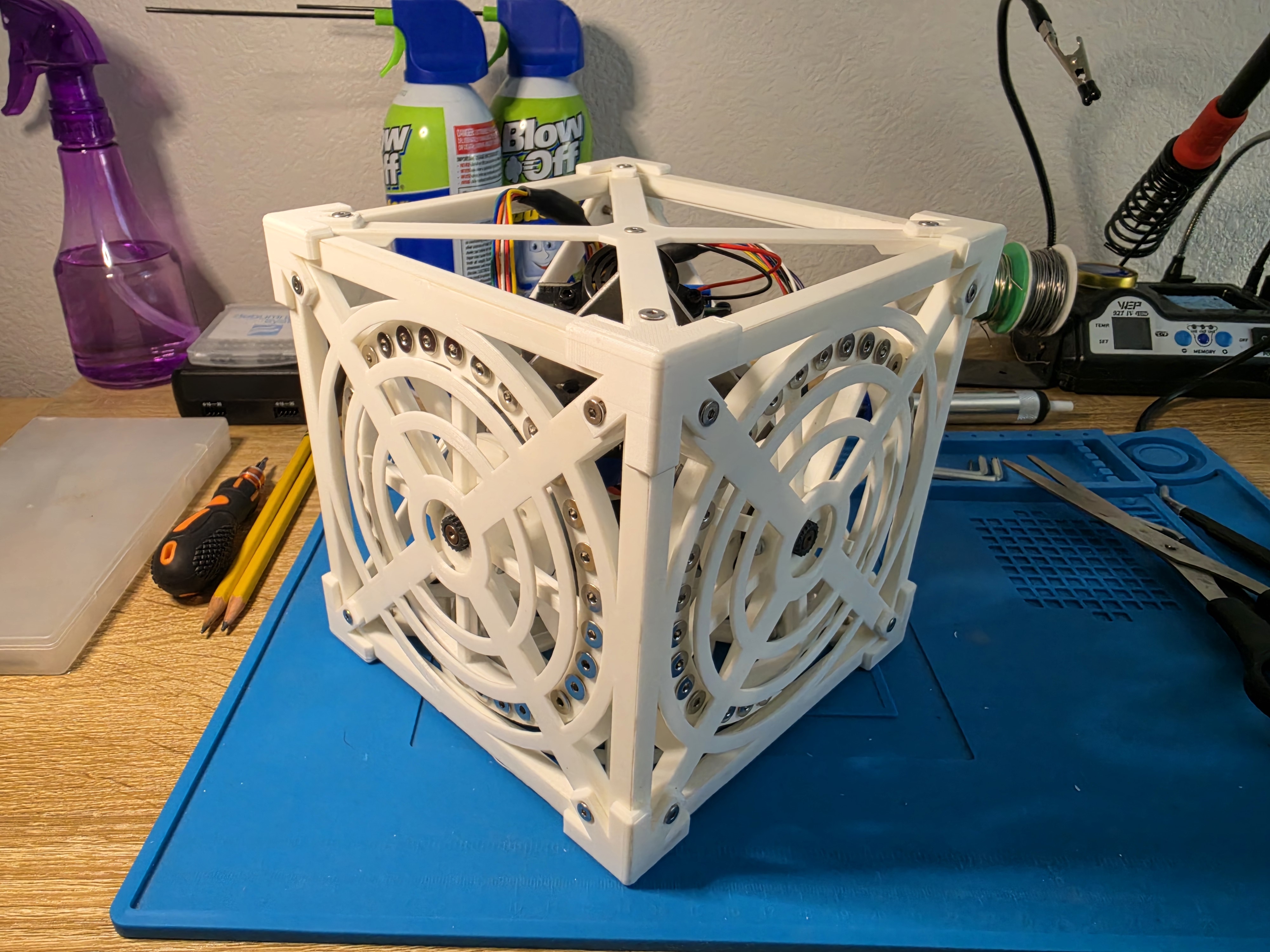
Cubli is the first of my projects for which I will use my portfolio as running documentation for. Cubli is inspired by the project of the same name developed at ETH Zurich by the Institute for Dynamic Systems and Control. Using a set of 3 reaction wheels, this robot should be able to balance on a corner. While on a corner, it should also be able to slowly rotate cw/ccw. ReM-RC’s video demonstrates what this balancing should look like, though he does not track yaw angles. As someone who wants to fly satellites, I figured this project was a decent way to get my hands dirty and get some fun ADCS and firmware experience under my belt.
The emphasis of this project is solely on dynamics, state estimation, and controls. I want to give a HUGE thank you to ReM-RC for open-sourcing the hardware for this awesome project. His version is fundamentally similar to the research-grade hardware of ETH Zurich, except redesigned with cheap, accessible COTS parts. All of the part files and schematics for his project you can find on his github repo. I did make a few hardware modifications to this project which you can find on my repo.
I didn’t just follow ReM-RC’s documentation and work instructions to a T. That would make this project meaningless and no more of an exercise in engineering than a lego set is. I am building custom controllers. A quick glance at RemRC’s controller firmware shows that he used a simple, effective, model-free, and well-tuned proportional controller on both gyroscope and accelerometer readings. While that certainly works, I’m an idiot and intentionally want to shoehorn in advanced controllers. I want to model the dynamics of the cube and at least TRY to implement literally every type of controller I know: P, PI, PID, pole-placement, LQR, MPC, H-$\infty$, Adaptive Control, hell if I design a rig that automatically stands the cube back up to its equilibrium point even a RL policy is on the table! Such ambition… get to work!
When completed, I want this to be my magnum opus personal project. Unlike many of my other posts, the intended audience for this post are people in the robotics/GNC field and contains a lot of deep technical concepts sans explanation.
Mechanical Parts
ReM-RC designed 90% of my cube. Annoyingly, all his original Thingiverse files are already non-parametric .STLs. I reverse-designed them to be parametric Onshape files :). I also designed some additional parts of my own you can find below.
If you have an Onshape account (free), you can export, or copy + modify any of the parts below.
- Original ReM-RC hardware reverse-engineered and modifiable: most of the original hardware is here
- Custom Cubli corner bracket: to protect cubli sharp corners
- Custom Cubli battery hardstop and speaker holder: battery hardstop and speaker holder combined into one part
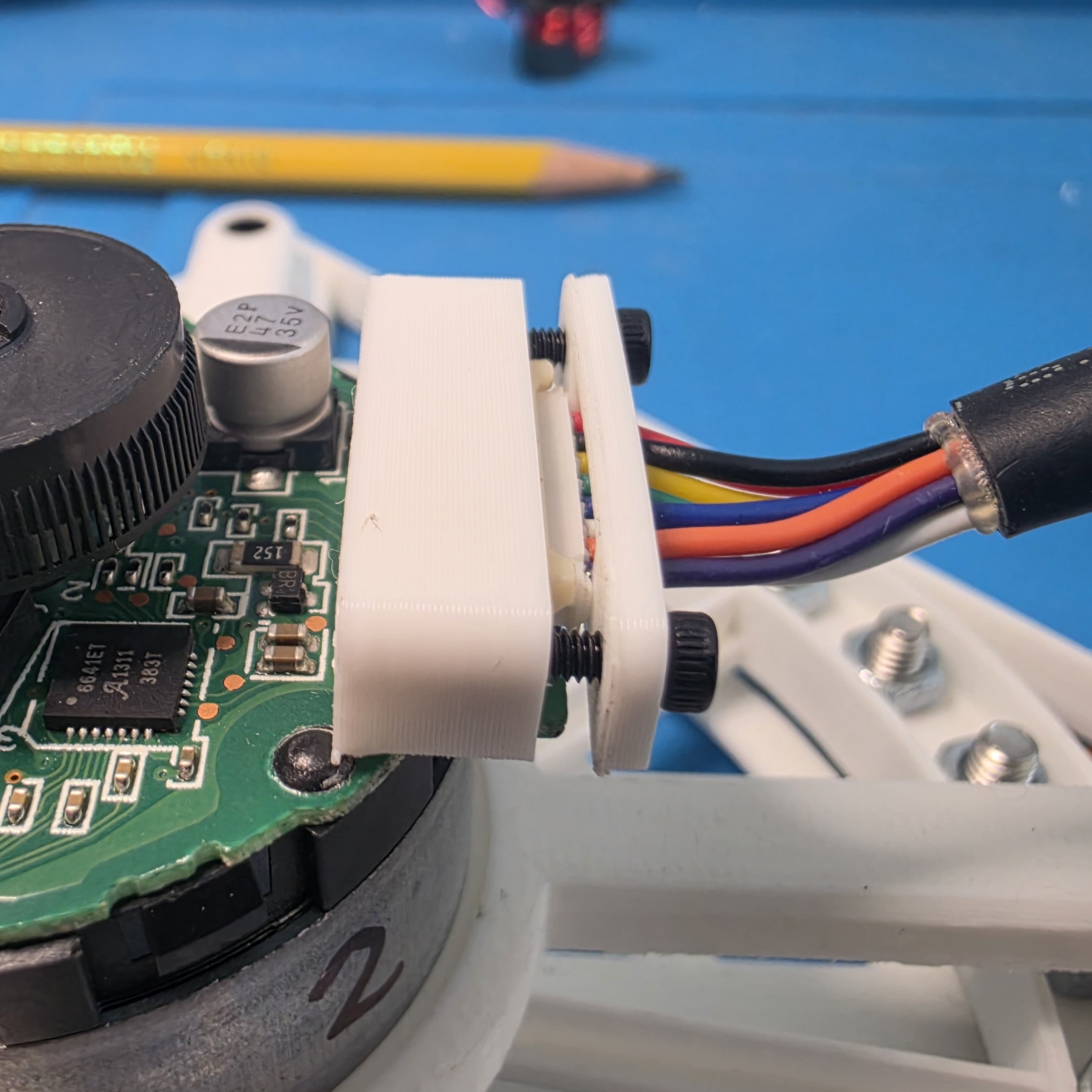
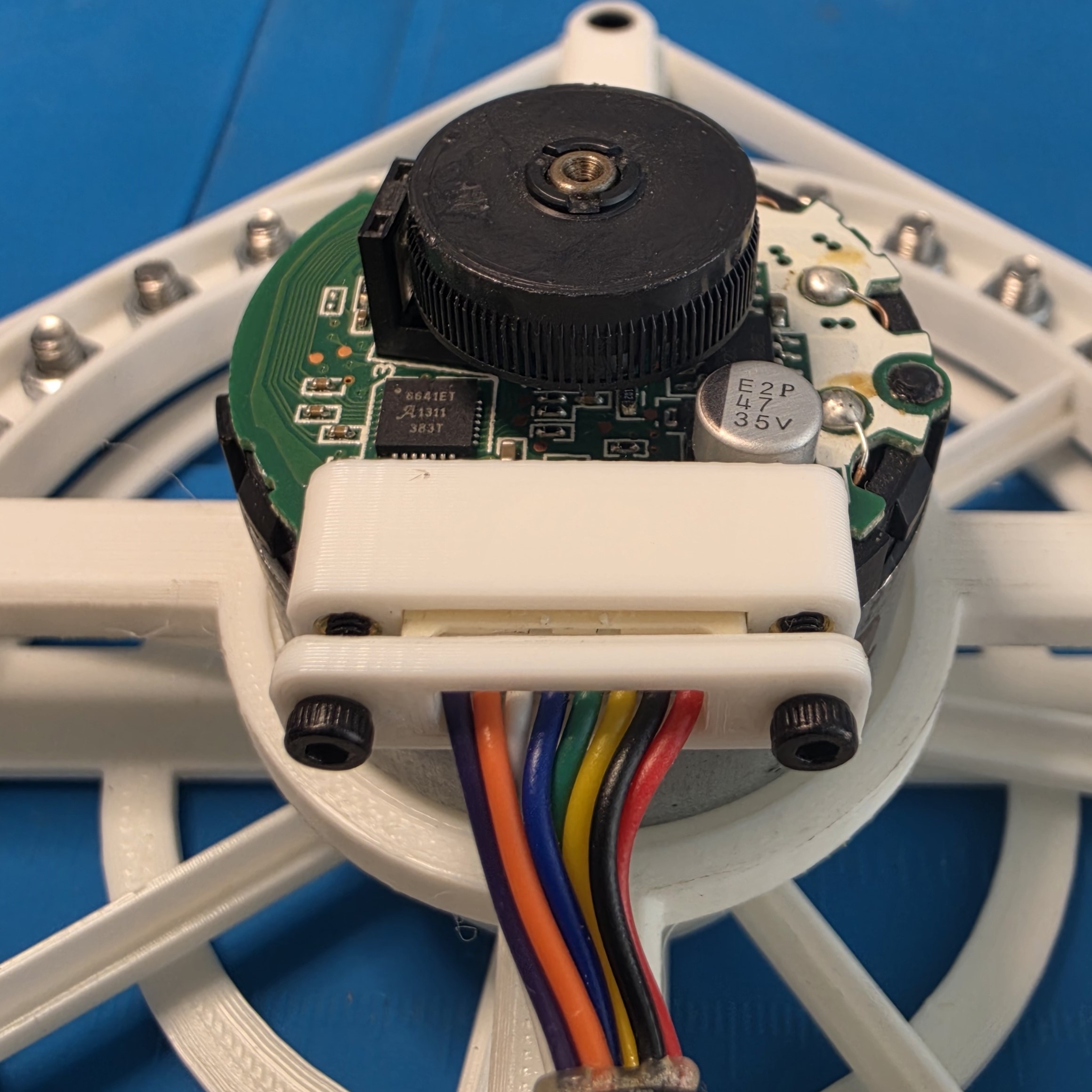
- Custom Cubli NIDEC motor connector retainer: because the connector kept disconnecting from the motor
Most parts FDM printed in PLA and joined via heatset threaded inserts. Larger flat plate-like parts laser cut out of aluminum.
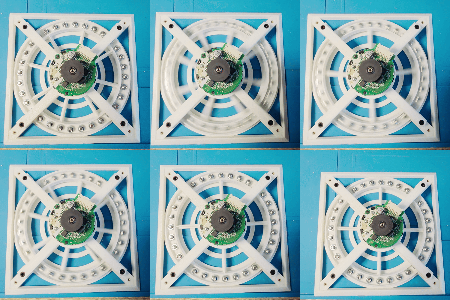
Here’s a quick gif to appreciate ReM-RC’s design: the flywheel runs clear and true
Electronics
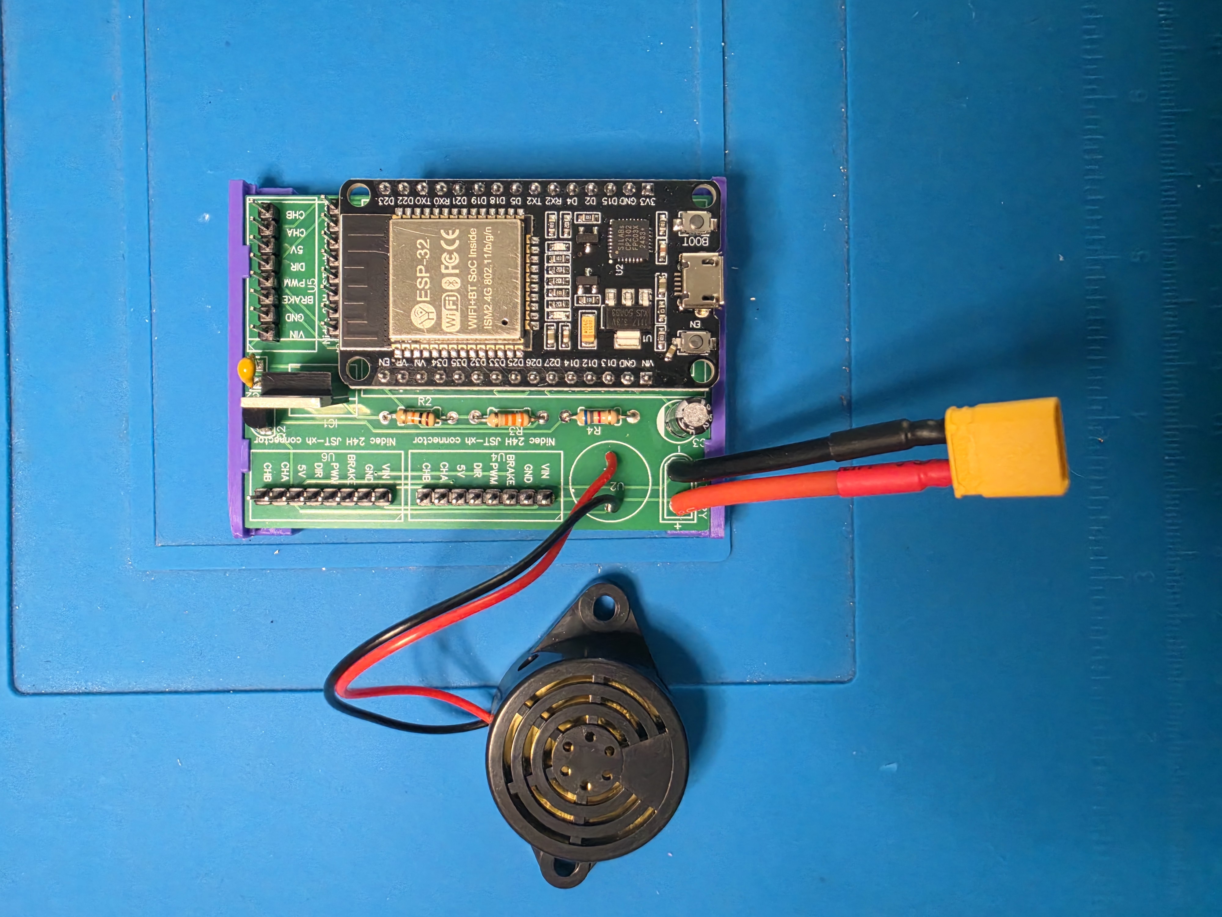
Again, credit to ReM-RC for hardware scoping and design. Also, a quick shoutout to oshwlab user malebuffy for design of the cubli breakout board and saving me the headache of soldering a thousand pins myself on a DIY PCB. Manufactured by JLCPCB.
- Motors: 3x NIDEC-24H BLDC motors. 2-channel Encoded. PWM speed control. Binary braking and direction pins. The full datasheet is here.
- Sensor: MPG6050 6-DoF IMU on an Arduino breakout. I2C bus.
- CPU: ESP32-WROOM-32
- Power: 12.5V 650 mAh 3 cell LiPo battery (classic for drones)
- Peripherals
- Voltage divider for battery sense
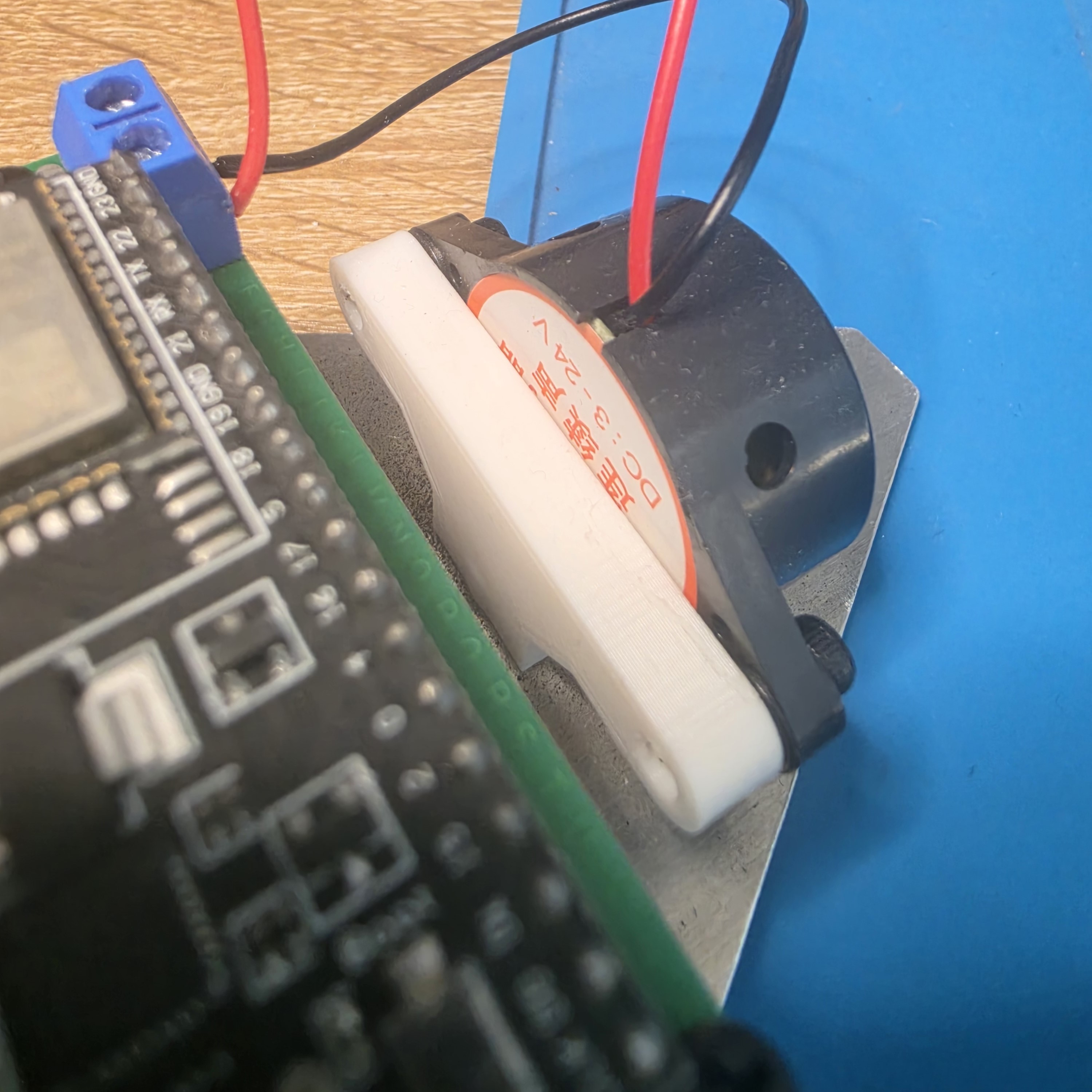
- Buzzer for simple user information relay (eg: 1 buzz for calibration mode, 2 buzz for starting control loop, continuous beep for low-battery)
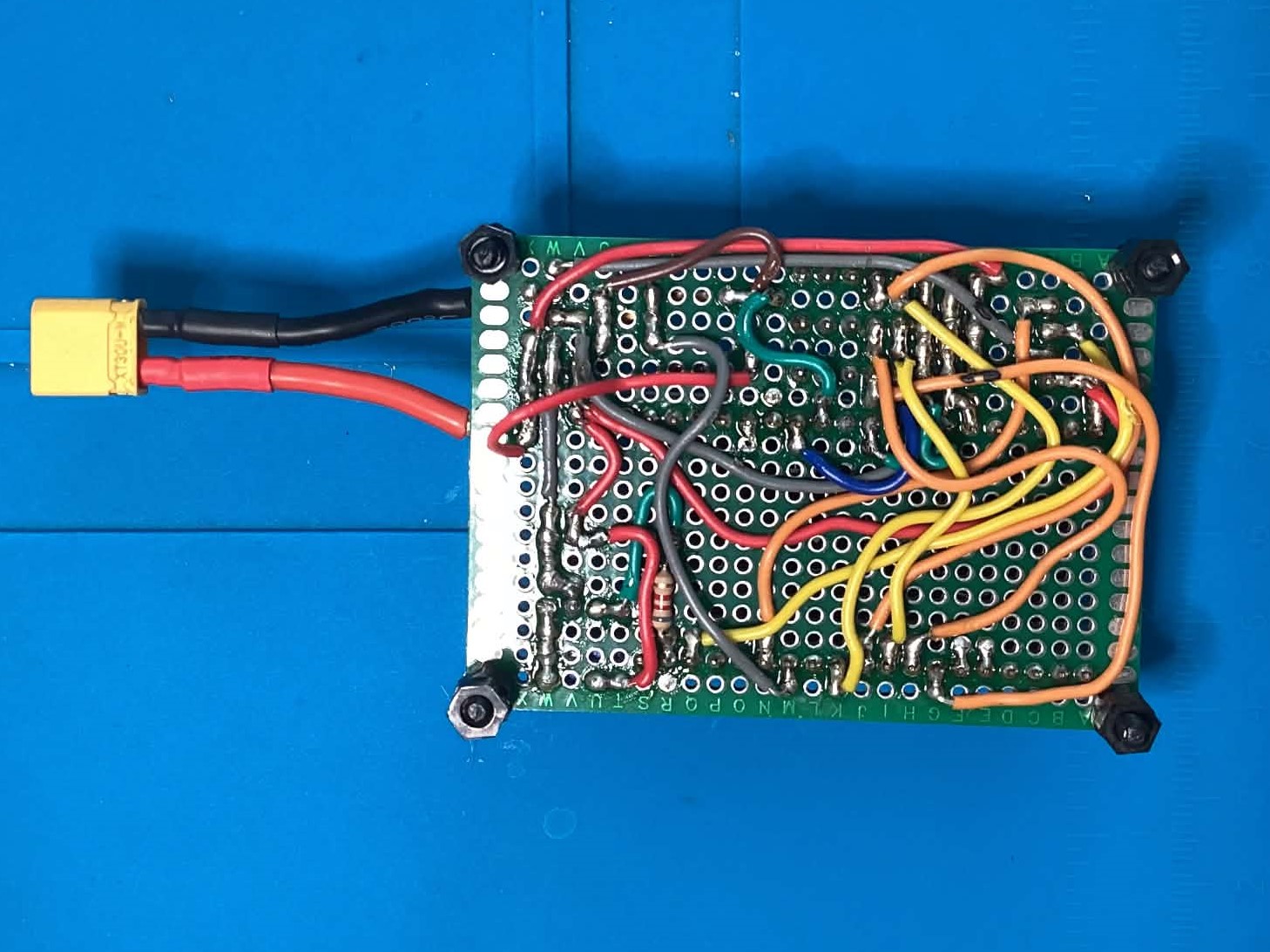
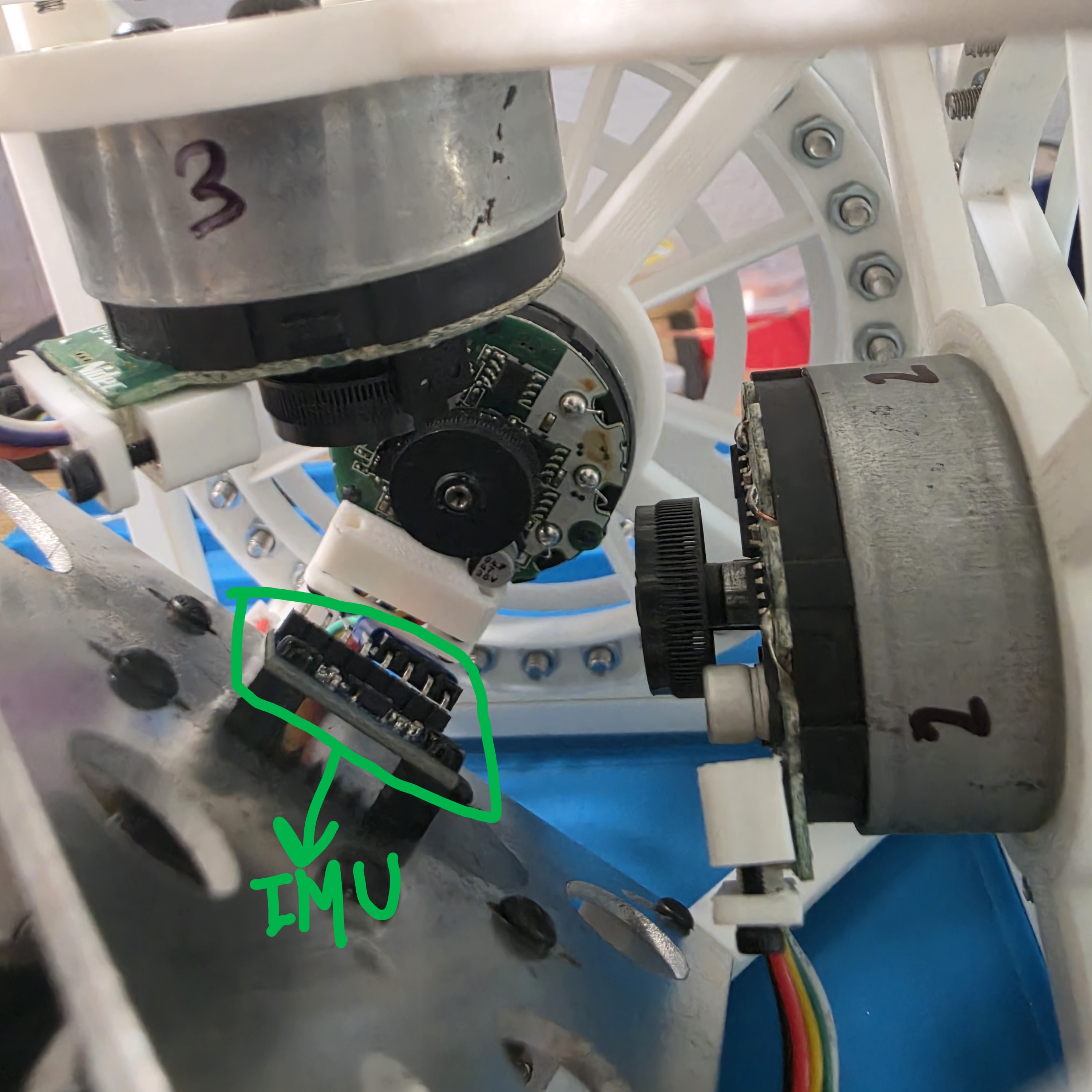
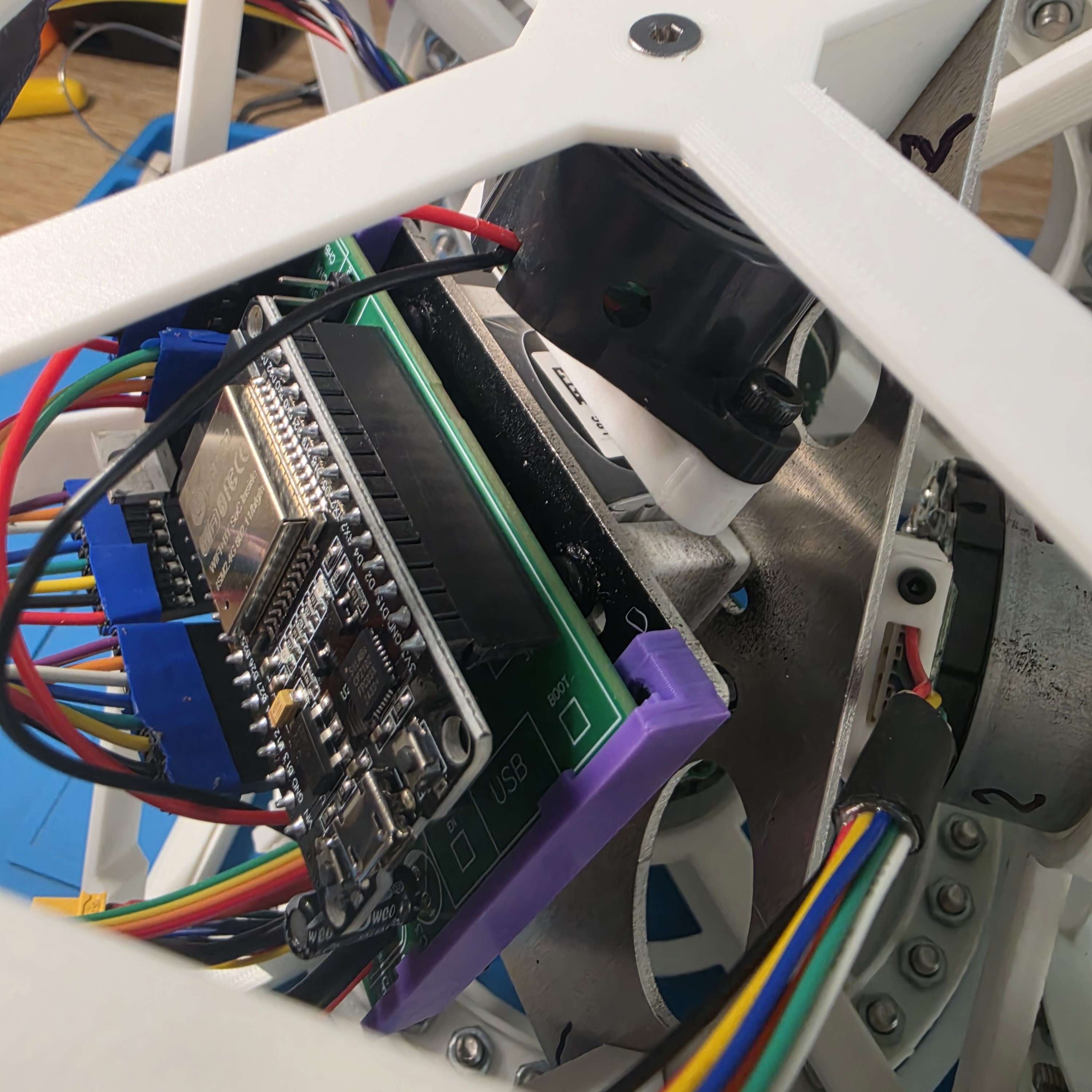
Firmware
This section onward is where my own work truly begins and I diverge from ReM-RC.
In the past, I always flashed to ESP32s using the USB cable and also used the same cable as my data connection for Serial. I would have gone crazy if I needed to do that for Cubli. Not only because I iterate and flash frequently, but more critically because I would need IMU data streamed back to me without the mechanical attachment of a cable affecting Cubli’s dynamics. Platform.IO is a way to flash over wifi and mosquiTTo is a way to publish and subscribe to OTA messages (not dissimilar to ROS).
Platform.IO and mosquiTTo reminders
The workflow for OTA flashing
- Open the project in Platform.io (the folder must contain a file
platformio.ini) - Make sure
platformio.inicontains at least the following[env:esp32dev] platform = espressif32 board = esp32dev framework = arduino # comment the next two lines to upload via USB upload_protocol = espota upload_port = 192.168.0.220 - compile and upload (check mark and arrow in bottom left of VSCode Window)
The workflow for OTA IMU data readout
- Open a terminal and run
& "C:\Program Files\mosquitto\mosquitto.exe" -c "C:\mosquitto-config\mosquitto.conf" -v. All this does is start mosquiTTo - Open a new terminal and run
& "C:\Program Files\mosquitto\mosquitto_sub" -h localhost -t esp32/accelfor live IMU readouts. - ALTERNATIVELY, run
python log_imu.pyand then runpython analyze_imu.pyif running a proper system ID test.
Reminders
- to make sure ArduinoOTA is not locked out of the ESP32:
- Every
main.cppwrapper flashed to the ESP32 must contain#include <ArduinoOTA.h> - Every
void setup()method needs to containArduinoOTA.setHostname("esp32-imu"); ArduinoOTA.begin(); - In as many places as possible within
void loop(), especially where you may get stuck within a conditional, addArduinoOTA.handle(); - essentially, the firmware needs to no only be executing the control loop but must always be listening for new code too.
- Every
- Troubleshoot: if will not upload OTA, check in order
- ping the IP address and see if you get a response, if no response, reset the ESP32 and try pinging again
- use IP scanner to see if address has changed.
- check for Windows system Firewall (may have been reactivated after software update)
- check for brownout (insufficient power to ESP32 due to depleted battery)
- check for
ArduinoOTA.handle();blind spots - ask Claude
- Troubleshoot: if cannot get messages back
- Make sure
esp32/accelmatches themqtt_topicinmain.cpp - run
net stop mosquittoand try again (essentially restart mqtt).
- Make sure
Modeling and Dynamics
This is where the fun begins. A lot of dynamic modeling is analytical derivation. Full derivations can be found on the document linked below. On this page you will find key design decisions and results. Another large chunk of modeling is empirical, and involve experimental design and data collection. You will also find those experiments and their results here.
Nomenclature and Values (for quick reference)
Experimental Values (Cubli intrinsics)
Analytical Variables
Frames of Reference
I defined 4 frames of reference for this project. All are outlined below. All are right-hand convention cartesian.
- $AF$: Accelerometer frame, the frame of reference with origin and axes aligned with the MPU6050’s sensor axes. Rotates with body
- $TF$: Torque frame, the frame of reference with axes aligned with the direction of torque applied by the wheels. Rotates with body
- $O$: Inertial frame, sits at the pivot origin and is well… inertial
- $O’$: Body frame, initially indistinguishable from $O$, and is used as the primary FoR for cubli’s state. Rotates with body
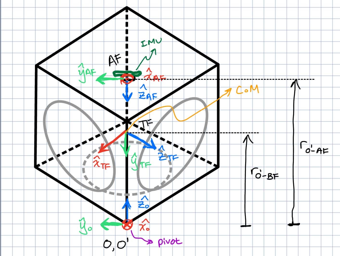
A few extra notes for clarity
- $AF, TF, O’$ are all fixed relative to each other. So the direction cosine matrix between each is static.
- $TF$ in the figure is centered on the CoM of cubli, but this is technically not a requirement, since torque is a free vector.
Desired State-Space Realization
At the center of EVERYTHING for cubli is its state space (SS) realization. Let’s rip the band aid off.
\[\begin{align*} x &:= [\theta, \phi, \psi, \dot{\theta}, \dot{\phi}, \dot{\psi}, \tau_1, \tau_2, \tau_3]^T \in \mathbf{R}_{9\times 1}\\ y &:= [a_x, a_y, a_z, g_x, g_y, g_z]^T_{AF} \in \mathbf{R}_{6\times 1}\\ u &:= [\tau_{1c}, \tau_{2c}, \tau_{3c}]^T_{TF} \in \mathbf{R}_{3\times 1}\\ \dot{x} &= [A_{9\times 9}]x + [B_{9\times 3}]u\\ y &= [C_{6\times 9}]x + [D_{6\times 3}]u \end{align*}\]Getting the easy out of the way first, the definition for $y, u, A ,B, C, D$ should not require too much explanation.
- $y$ is my observation (measurement) vector and is simply the 6 raw numbers output by the MPU6050. $a_i$ is linear acceleration along the $i$th axis [kgm/s^2] and $g_i$ is the angular velocity about the $i$th axis [rad/s]. For clarity, I indicate that this vector is expressed in $AF$ using subscripts.
- $u$ is my control input command vector and consists of the desired torque I want the 3 motors to output. I indicate that this vector is expressed in $TF$, so each scalar term $\tau_{ic}$ corresponds directly with the output motor $i$.
- $A, B, C, D$ complete my linear state space model. Of course, at this point I haven’t found them yet, and doing so will be sooo fun.
Justifying my choice of state vector definition $x$ requires deeper clarification and rationale.
- $\theta, \phi, \psi$ correspond to $X-Y’-Z’$ euler angles respectively, and (assuming a stationary pivot point such that $O$ and $O’$ origin remain coincident) track the attitude of $O’$ relative to $O$ and hence Cubli’s attitude.
- I did not use quaternions even though they are standard practice in aerospace because I am solving a regulation problem where my system stabilizes at $\theta = \phi = \dot{\theta} = \dot{\phi} = 0$, so I felt quaternions for the sake of avoiding a singularity (which occurs at $\phi = 90^o$ for this particular Euler Angle convention) I never expect to come close to would be unnecessarily complicated. Also I still kinda fear quaternions because they are so physically unintuitive.
- $\psi$ is a state I leave free. At the balancing point, $\psi$ will look like cubli’s yaw angle. Cubli needs to be able to track external yaw angles provided by me while maintaining balance.
- I augmented my state with $[\tau_1, \tau_2, \tau_3]$ even though they are not intrinsically encoded within cubli’s free dynamics because otherwise, $D\neq 0$ which is something I am trying to avoid. In general, it is standard practice to have $D =0$ since not doing so means when feeding back on the error term, $u’ = K(y(u) - x)$, meaning the new control input becomes a function of the old control input, which can cause a host of problems in an unideal system with noisy actuators. Why $D\neq 0$ without the augmented states is not immediately obvious but becomes clear when you start actually trying to derive the measurement model $C$. The reasoning is
- $a_i \in y$ is certainly dependent on the angular acceleration of the cubli ($\ddot{\theta}, \ddot{\phi}$).
- $\ddot{\theta}, \ddot{\phi}$ would both be dependent on $u$ in an unaugmented state vector definition.
- this makes $a_i$ indirectly a function of $u$, which is a nono
- I want to emphasize that $\tau_i$ in $x$ is different from $\tau_{ic}$ in the $u$. $\tau_i$ is the torque that motor $i$ is CURRENTLY outputting, while $\tau_{ic}$ is the new torque COMMAND (hence the $c$ subscript) the controller is telling motor $i$ to achieve. There are empirical methods to ID this first-order transient behavior between $\tau_i$ and $\tau_{ic}$ which are touched on later.
Dynamics Model $A, B$
Now let’s derive $A$ and $B$ matrices. This is where I hide all the algebra, rotation matrices, and partial derivatives in my pdf document and spare you the eyesore. In short, the process is
- Convert Euler Angle rates $[\dot{\theta}, \dot{\phi}, \dot{\psi}]$ to a body-frame angular velocity $\omega_{O’}$.
- Set up and solve the resulting Lagrangian Mechanics problem which will yield a set of equations where $\ddot{\theta} = f(x)$. And likewise for $\ddot{\phi}$ and $\ddot{\psi}$.
- Take a small-angle approximation on $\theta, \phi$.
- Jacobian linearization about ($\theta = \phi = \dot{\theta} = \dot{\phi} = 0$)
The final system dynamics written out explicitly is
\[\begin{bmatrix} \dot{\theta} \\ \dot{\phi} \\ \dot{\psi} \\ \ddot{\theta} \\ \ddot{\phi} \\ \ddot{\psi} \\ \dot{\tau_1} \\ \dot{\tau_2} \\ \dot{\tau_3} \end{bmatrix} = \begin{bmatrix} 0 & 0 & 0 & 1 & 0 & 0 & 0 & 0 & 0\\ 0 & 0 & 0 & 0 & 1 & 0 & 0 & 0 & 0\\ 0 & 0 & 0 & 0 & 0 & 1 & 0 & 0 & 0\\ \frac{mgr}{I_1} & 0 & 0 & 0 & -\frac{I_{zz}}{I_1}\dot{\psi} & 0 & -\frac{\sqrt{6}}{6I_1} & \frac{\sqrt{6}}{3I_1} & -\frac{\sqrt{6}}{6I_1}\\ 0 & \frac{mgr}{I_1} & 0 & \frac{I_{zz}}{I_1}\dot{\psi} & 0 & 0 & \frac{\sqrt{2}}{2I_1} & 0 & -\frac{\sqrt{2}}{2I_1}\\ 0 & 0 & 0 & 0 & 0 & 0 & -\frac{\sqrt{3}}{3I_{zz}} & -\frac{\sqrt{3}}{3I_{zz}} & -\frac{\sqrt{3}}{3I_{zz}}\\ 0 & 0 & 0 & 0 & 0 & 0 & -\frac{1}{t_{TC}} & 0 & 0\\ 0 & 0 & 0 & 0 & 0 & 0 & 0 & -\frac{1}{t_{TC}} & 0\\ 0 & 0 & 0 & 0 & 0 & 0 & 0 & 0 & -\frac{1}{t_{TC}}\\ \end{bmatrix} \begin{bmatrix} \theta \\ \phi \\ \psi \\ \dot{\theta} \\ \dot{\phi} \\ \dot{\psi} \\ \tau_1 \\ \tau_2 \\ \tau_3 \end{bmatrix} + \begin{bmatrix} 0 & 0 & 0\\ 0 & 0 & 0\\ 0 & 0 & 0\\ 0 & 0 & 0\\ 0 & 0 & 0\\ 0 & 0 & 0\\ \frac{1}{t_{TC}} & 0 & 0\\ 0 & \frac{1}{t_{TC}} & 0\\ 0 & 0 & \frac{1}{t_{TC}}\\ \end{bmatrix} \begin{bmatrix} \tau_{1c} \\ \tau_{2c} \\ \tau_{3c} \end{bmatrix}\]Measurement Model $C, D$
Unlike dynamics modeling, measurement modeling is strictly a kinematics problem. Again, there is no shortage of mathematical gymnastics that you need to find in my pdf, but most of the work here is simply knowing how to apply the golden rule of rotational kinematics
\[a_r = a_s - \alpha \times r - 2 (\omega \times v_r) - \omega \times (\omega \times r)\]The final measurement model written out explicitly is
\[\]$I_w$ Calcs
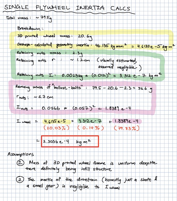
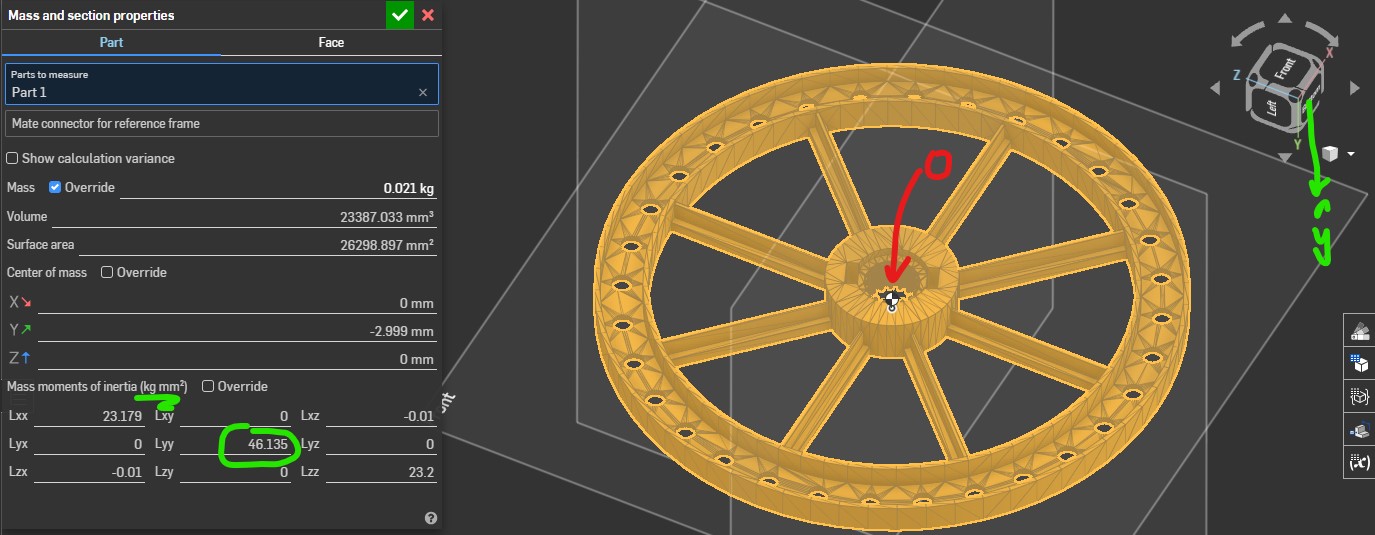
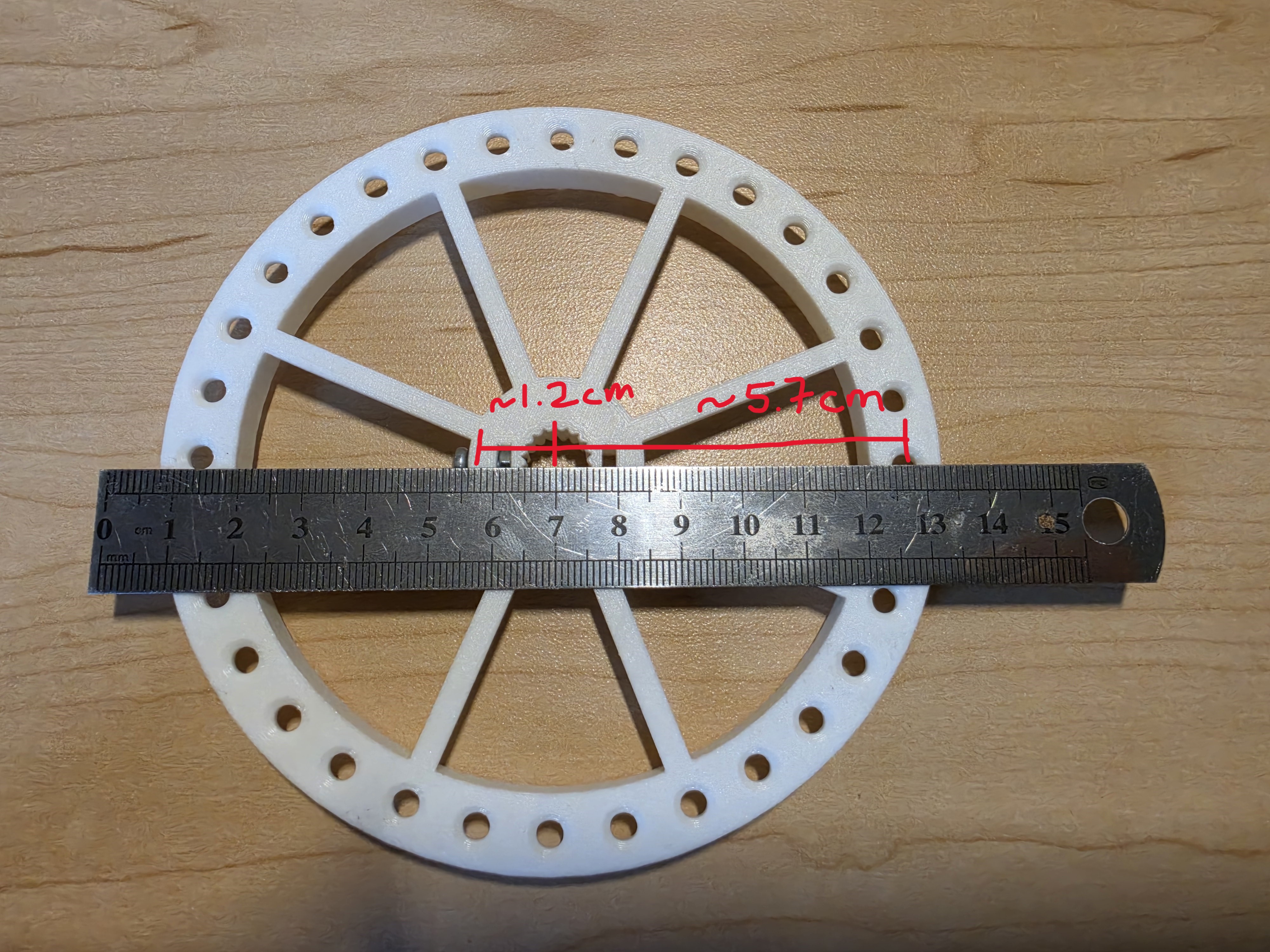
Analysis is done (for now) and I need to get to know Cubli nice and personal. Low hanging fruit is the rotational inertia of the flywheel. I need this because eventually I am going to allocate $\alpha_i$ from my motor encoders to $\tau_i \in u$ and to do this I need $I_{w}$ to apply $\tau_i = I_{w} \alpha_i$.
Honestly this step is so trivial I am just going to spam you with my hand-calcs and some pictures I took for documentation purposes. $\boxed{I_{w} \sim 2.3036*10^{-4} ~\text{kg m}^2}$.
Finding the $I_c$ tensor and $r_{CM}$
The problem of finding the inertia tensor of cubli has allowed me to exercise some creativity in experimental design. Since all of my kinematics/dynamics are calculated wrt $O’$, that is also how I define $I_c$. Now ideally I would have a perfect CAD model with all the right mass properties set or overridden such that a simple computer evaluation would give me $I_c$, but I do NOT have this luxury (this is something I may do in the future ONLY if necessary aka I need a more precise inertia tensor).
The overall problem is that I need to find \(I_c = \begin{bmatrix} I_{xx} & I_{xy} & I_{xz}\\ I_{yx} & I_{yy} & I_{yz}\\ I_{zx} & I_{zy} & I_{zz} \end{bmatrix}\)
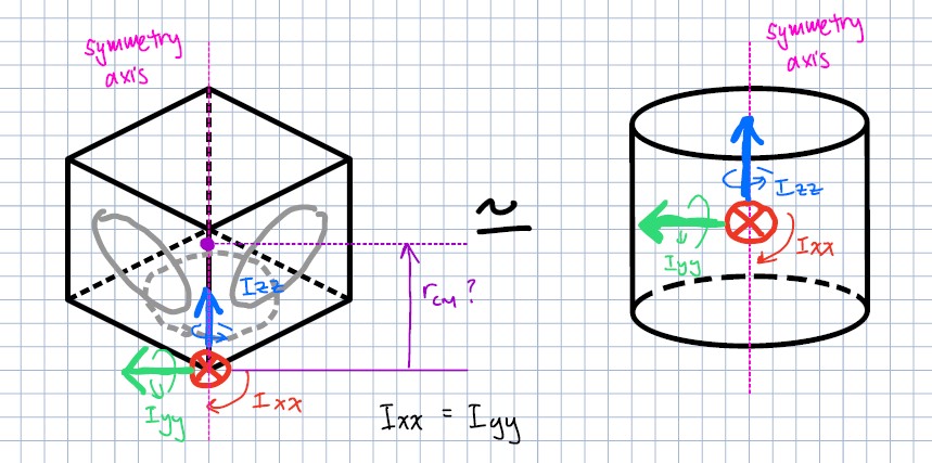
Where $I$ is symmetric by nature so that $I_{ij} = I_{ji}$, leaving only 6 unique terms to find. BUT, I make the relatively safe assumption that Cubli is rotationally trisymmetric about the z-axis of $O’$, implying $I_{xx} = I_{yy}$ and also that the z-axis of $O’$ is a principal axis of rotation! This simplifies $I$ to be
\[I_c = \begin{bmatrix} I_{xx} & 0 & 0\\ 0 & I_{xx} & 0\\ 0 & 0 & I_{zz} \end{bmatrix}\]Voila! I need only to identify 2 inertia terms of my Cubli! Observing $A$ we also see that I will need $r_{CM}$ the location of the center of mass of cubli, which per the rotationally symmetric assumption, should also lie on the z-axis of $O’$. The value hunt begins!
Finding $I_{zz}$
$I_{zz}$ is the relatively easiest value to find. Since I know $I_w$ and all 3 motors are encoded,
Finding $I_{xx}$ and $r_{CoM}$
havent gotten around to documenting yet, but here’s a sneak peak