Sean's Engineering Portfolio
Towers
Towers (or any of the Science Olympiad structure events), has a simple premise. The goal is to build a weight-bearing structure that meets minimum width/height dimensions that has the highest structural efficiency. This efficiency is defined as the mass held (g) / mass of the structure (g). As a simple example, if a tower holds 10 kg and weights 10 g, the efficiency of the tower is 10,000 / 10 = 1000.
For two years of high school, I poured my heart and soul into this event. It is perhaps the most tedious event in Science Olympiad when taken seriously, and I took this event very seriously. In fact my personal goal was to place in the top 3 at Nationals, the highest level of competition in Science Olympiad. I spent upwards of 10-15 hours a week building the tower to extreme precision, and each week I would test the tower to failure. Using slow motion cameras, I would identify the point of failure on my structure and reinforce that particular spot on next week’s design iteration. This cycle of building and breaking would repeat week after week until competition, where I would take my most successful design iteration, create an exact replica, and compete. It may seem unreasonable to spend 10-15 hours building a simple balsa wood structure that seems like it can be whipped up in less than an hour with sticks and super glue. However, I was striving for PERFECTION. Operating under the assumption that construction is flawless, the design is the differentiating factor. Choice of wood density and truss structure become the crux of the event. Unfortunately, when building these structure by hand, construction is NOT flawless. A perfect truss design can easily be ruined by poor craftsmanship and slightly bowed main beams. Therefore, the majority of my efforts during construction were focused on building pristine craftsmanship. Perfection requires time. As an example, I would spend 45 minutes simply choosing which sticks I wanted to use. I made sure the density was just right as well as evenly distributed before I was comfortable making my tower out of it. Fortunately, I will not bore you with the minute intricacies of my construction process or every single iteration of my design. Instead, I present my two most successful designs each year of competition.
2017
The specifications of the event in 2017 were simple. The tower had to be a minimum of 60 cm tall, and the tower had to span a 15 cm * 15 cm square hole at the base. The top of the tower had to accommodate a 5 cm * 5 cm square block on top, from which weight would be added. The tower was allowed to hold up to 15 kg, but any more mass than 15 kg would not be considered. However, there is the possibility of a bonus. If the tower’s base instead could span a circle of diameter 25 cm, there would be a 5 kg bonus added to the final weight held.
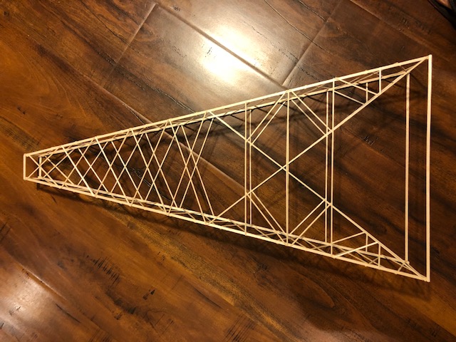
Pictured above was my final tower design that I took to the national competition. As you can see, I decided to go for the 5 kg bonus as the base of my tower is not a square and is intended to span a circle of 25 cm. In competition, it was common for teams to use 3 different base geometries. The first was the one that I used, a simple longitudinal rectangle that achieved the bonus. The second is a simple square base that barely spanned the 15 cm * 15 cm square hole from midpoint to midpoint. The third was a base similar to mine in that it was rectangular. However, this base only intended to span the 15 cm square, thus not achieving the bonus. The theory behind the bonus is simple: when the base that needs to be spanned is wider, the main beams of the tower need a more extreme taper towards the fixed dimensions of the top of the tower. The more extreme the taper, the less weight the tower will hold.
The final question I get about this design is: why this particular truss structure? It is common to gravitate towards an “X” truss or a “Z” truss in civil engineering. My answer is nothing glamorous and carefully calculated. I chose this truss structure because I saw it on a power tower once XD. I actually tried the “X”, “Z”, and power tower-inspired design and the last actually proved to use the least material! Yet, it proved enough for the purposes of competition. Why reinvent a structure that has been tried and tested by professionals?
2018
The specifications of the event in 2018 in fact did not change from the previous year except for one key difference. The tower was no longer allowed to have a single continuous beam from head to toe. Instead, it had to have a discontinuity at at most 20 cm from the base. The top section of the tower now had to be straight and the bottom section needed to be tapered in order to meet the base dimension specifications.
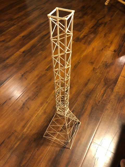
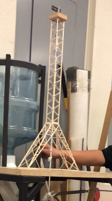
As you can see, I had multiple final designs in 2018. My first design was clearly not as ambitious as the second, only aiming to meet basic specifications with no fancy truss structure. I chose to use evenly spaced “X” trusses for the bottom section and a simple zig-zag pattern of trusses for the top section. The trick with these towers was actually the precision. After a year of tower-building experience, I decided to create a jig that would help me maintain perfect beam straightness as I glued the trusses on the top section. The bottom section was created separately, and the trickiest aspect of this entire process was making sure the top and bottom sections aligned perfectly and level. Imperfect alignment meant that the beam cross sections at the discontinuity would not see complete coverage, causing potential for failure at the joint. Imperfect levelling would cause the straight section of the tower to rest at a tilt, causing for a disastrous failure due to imbalance. Regardless, once I got the craftsmanship down, this trivial design proved extremely effective.
The second design is visually more interesting and attempts to yet again achieve the 5 kg bonus by spanning additional distance at the base. The biggest issue here was that the taper of the bottom section was extreme, and much more of a handicap than for 2017’s tower. Ultimately, my truss design for the bottom tapered section drew inspiration from my 2017 tower design as well as tips from my physics teacher, not to mention trial and error. Traditional truss structures are great for preventing vertical or near-vertical beams from bowing in any direction, essentially acting as braces that keep the main load bearing beams straight. The taper of this tower is too far from vertical for the type of failure to be beam-bowing. Instead, the beams are much more likely to simply fail by shear stress. As such, the justification for my supports that hug close to the tapered beams is rather to reinforce the shear strength of the beams rather than prevent them from bowing.
I ended up using my first design at the national competition, which was a mistake in retrospect. This design gave me my highest efficiency score throughout the season, and I was hoping it would repeat its earlier success. However, the issue with the first design is that it is too reliant on certain factors that I cannot control. Without the grace of a bonus, this design’s merit was justified almost solely by its light weight. Due to this, I was forced to use very light and unevenly dense sticks, making room for unexpected and uncontrollable points of low-density. The second design, though it did not have as high of a peak efficiency, was more stable. The certainty of 5 kg of added bonus as well as the necessity to use heavier sticks, which are more reliable and homogenous in density.
Reflections
Tower building was unquestionably the Science Olympiad event I was most dedicated to. In a way, I regret spending so much time trying to perfect a design as I chased a superficial medal. The desire of being presented the award on-stage was motivated by vanity. Aside from the initial ideation of the design and truss structure I would use, I did not learn anything from the repetitiveness. I sometimes wonder at the opportunity cost of my unhealthy dedication. I was sacrificing quality time with friends and family in order to perfect my craftsmanship. Regardless, I can proudly say that I do not regret the experience as a whole. The spirit of Engineering is all about patience and resilience towards failure. Perfection is not achieved overnight, and the years I spent building structures for Science Olympiad have driven that home hard.
| 2017 Design | 2018 Design 1 | 2018 Design 2 | |
|---|---|---|---|
| Tower weight (g) | 6.28 | 4.90 | 6.80 |
| Load held (kg) | 12.8+5 | 15 | 13.9+5 |
| Efficiency | 2,834 | 3,061 | 2,779 |
| Standings | 4th Nat. | 1st MIT | 1st State |
Mousetrap Vehicle
Mousetrap Vehicle is, without question, my favorite Science Olympiad engineering event. The event has endless room for creativity and is the most open-ended of the Science Olympiad engineering events. As well, it does not require the hours upon hours of boring and repetitive work that building a wooden structure requires. Perfecting my vehicle became my number one priority during my senior Science Olympiad season. In fact, as others were too busy not being busy (due to senioritis), I was spending an hour after school every day driving my physics teacher nuts as he constantly dodged the rat-like contraption zooming around his classroom.
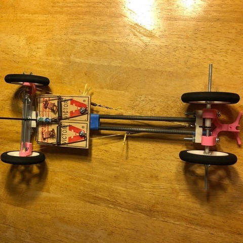
Now, I know what you may be thinking: mousetrap vehicles are such a typical physics project, even I made one in high school. This is where I need to step in and explain the difference, out of respect for the countless hours former me spent engineering and calibrating a car that I assure you is not as crude as the CD-wheeled monstrosities that you saw in your physics class. Firstly, the objective of my car was not only to get it moving, but to have it move fast and stop at accurate intervals. You may notice that there is a vertical rod at the front of my vehicle which seems operationally unnecessary. You are correct, however for competition purposes this is the “reference point” on the vehicle. The track was set up as a straight line with 0 m as the starting point, 12 m as the cup target and a single additional final target. The objective for the car was to push an upside down paper cup as close to the 12 m point as possible (if the cup covered the cup target point, that would be considered perfect). The car was then to switch to reverse and get as close the the end point as possible. The end point was placed anywhere between 11 and 9 m along the straightaway and offset 50 cm perpendicularly to the right of the track. From the moment the mousetrap is triggered/the vehicle begins moving to the moment the vehicle comes to a full stop is the recorded runtime. Teams were placed based on accuracy of both the cup target point and the final target as well as their speed.
Total Score = Runtime (seconds) + Distance between cup and cup target (cm) + distance between vehicle and final target (cm)
Lowest score wins
The Basics
There are a couple fundamental tasks that all vehicles should be able to accomplish including moving, reversing, and stopping. First of all, the movement of the mousetrap vehicle is accomplished by simply attaching a string to tip of the mousetrap and wrapping said string around the back axel of the vehicle. In order to extend the distance that the vehicle is able to travel (12 m is no laughing matter), the length of string wrapped around the back axel must be lengthened. As such, I decided to extend the arm of the mousetrap in order to make room for more string. Changing direction proved not to be as tricky as I originally thought. In fact, to change direction, all I did was attach a zip-tie to the back axel of the car. Using the knob of the zip-tie, I would wrap the string around it and change my winding direction. During the run, there would be a small click, and the vehicle would begin reversing. The task of stopping actually ended up being the trickiest. For traditional braking, I used a wingnut-bolt system with the bolt acting as the axel to my front wheels. This is a fairly well-known braking system for hobby cars that can accurately stop a car after X number of wheel turns. However, in this specific case, the traditional wingnut-bolt would fail as the car needed to stop somewhere in the middle of the return trip. Thus, the obstacle that stops the wingnut must be bypassed on the way to the 12 m cup drop-off and stopped ONLY on the way back. This called for a one-way obstacle in the path of the wingnut that could reliably stop the wingnut ONLY on the way back. A simple add-on to the traditional wingnut-bolt braking system sufficed.
Target Accuracy
From prior experience, I knew that getting the cup to the perfect 12 m spot was a MUST if I was to remain competitive with some of the top performers. Getting the cup to the 12 m mark exactly was a simple matter of calibration. After trial and error, I determined the perfect number of string wraps around the back axel to achieve exactly 12 m of travel distance before the string unwound around the zip tie and began moving the vehicle in the opposite direction. In fact, I uniformly spaced out a series of angular stopping points on my back wheels and color coded them to remember which point to set the vehicle to at the start position to achieve a perfect 12 m cup push.
Achieving accuracy on with the final target point was more difficult and was perhaps the most difficult aspect of the entire event. Hypothetically, if the final target point for the vehicle was placed along the straight line that spanned the starting and cup target points, the vehicle would need only to go straight and back up straight as well. However, due to the 50 cm offset towards the right, the vehicle had to move in a curve! In fact, this curvature needed to be adjustable as well! A final target point offset by 50 cm from the 11 m mark required a larger radius of curvature than one offset from the 9 m mark.
To accomplish the task of adjustable path curvature, I needed to make the front wheels of the vehicles rotatable. In addition, I attached two industrial grade chords to the ends of the front axel and looped the other end around a bolt towards the middle of the car. Along one chord, I inserted a spring and along the other, I inserted a length-adjusting screw. The matter of adjusting radius of curvature came down to toggling the length-adjusting screw. Interestingly enough, the changes in radius of curvature were so small between different final target points that I became lazy and just found a fixed radius that worked well for all points along the 9 m - 11 m range and rarely ever adjusted thereafter. Regardless, the adjustability factor still came in useful whenever I had to recalibrate the vehicle repeated use or sometimes even temperature and humidity differences!
Speed
The sad reality of Science Olympiad is that it is extremely competitive. I already expected most of the top teams at any competition to be able to land the cup target point beautifully and come within 10 cm of the final target point. Therefore, speed would become a crucial tiebreaker. “Speed”, however, is a misleading term. 12 m is a long distance, but 12 m is also short enough that the car would still be in the acceleration phase for the greater length of the track. For the first 12 m cup push, I needed high but controlled acceleration. Eventually, the vehicle would have to slow down and reverse direction, so I could not have the car build up so much momentum that changing direction would cause the car to skid. After the direction change, there was no holding back. The car could accelerate at lightning pace towards that final target point and rely solely on the brakes to stop (skidding would be taken into account during calibration).
To accomplish my desired acceleration, I made it a priority to use very lightweight materials on my vehicle. The body of my vehicle, other than the mousetraps themselves which accounted for most of the weight, was made with parallel carbon fiber rods which I acquired by cutting an arrow in half. Many of the other parts were manufactured using 3-D printing, so they were made of PLA. For wheels, I ended up using the lightest wheels I could find that did not sacrifice traction. Wheels such as CDs have too high of rotational inertia and offer very little traction. I used foam wheels. Finally, all wheel axels were mounted to the car using ball-bearings which significantly reduced frictional energy loss. In order to make the initial acceleration towards the 12 m cup target point controlled, I reduced the girth of the axel where the string wrapped around. This gives me smaller torque, and thus smaller acceleration, but more distance per angular actuation displacement of mousetrap. On the way back, I made the back axel extra thick. The vehicle would drop the cup off and fly in the opposite direction, releasing most of the wound up string very quickly and achieving the vehicle’s top speed in the entire run. Any additional distance was easily covered as the vehicle glided along by its own momentum, seeing very little deceleration due to the ball bearings minimizing friction.\
Results
Ultimately, my vehicle did not disappoint. I could always count on it to hit the cup target perfectly and be within 5 cm of the final target point, all the while running on anywhere between 9-10.5 seconds. That’s 13 - 15 m with a direction change in between travelled in 9-10.5 seconds with nothing but the energy stored in two mousetraps. This is my proudest Science Olympiad engineering accomplishment. I had a perfect streak with this vehicle for my entire season until the National tournament, taking 1st at every invitational and official competition until I was pushed to 2nd by Solon High School of Ohio on the National stage. I would be disappointed, but the truth was I saw their vehicle. It was an amazing feat of engineering that deserved the win. Their car could achieve the same accuracy of mine while using only 6 - 7 seconds of runtime. I would try to explain what I could see, but I’ll leave it to them to ever disclose their genius. In the meantime, it will remain a mystery to you. Props to you Solon :).
Chinook Helicopters
Helicopters was an event which I only dabbled in during my years as a Science Olympiad competitor. Due to my responsibilities in other events, our competition designs were always constructed by one of my teammates. However, I did build my fair share of Helicopters on my own just for kicks. This particular design is, in my opinion, my most interesting design and by far the one I enjoyed constructing the most.
For anyone who is unfamiliar with the classic design of these helicopters, I will explain briefly as well as redirect you to this link so you can check out the specifications yourself. The classic design that had reliably worked for competitors for years involved two co-axial rotors that rotate in opposite directions. Each rotor was comprised lightweight frame/ribbing and coated with an ultra-thin Mylar film. The power comes from a large rubber band loop which has been twisted hundreds of times and attaches to the two rotor hooks. A rigid balsa beam that is slightly offset from the center axis of the two rotors was used to connect the two rotors together. The competitor would traditionally hold the two rotors still during setup and simply walk to an open indoor space and release the helicopter for flight.
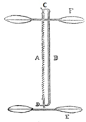
In fact, this design became so reliable that Science Olympiad created its own step-by-step kit that contains all the necessary materials and instructions for construction. The kit included thin carbon fiber rods and laser-cut wood pieces to optimize the weight of the helicopter and also included an extra rod attachable to the very tip of the top rotor to prevent the rotors from directly contacting the ceiling when flying (which could potentially damage the copter mid-flight). Due to the popularity of this kit design, I personally felt that much of the engineering spirit of the event became lost. Competitions saw team after team with identical designs come to fly, and the longest flight times ended up being awarded to the team that was able to make their helicopter the neatest. When the specifications (such as max rotor diameter and minimum helicopter weight) were changed between years, the kit would optimize accordingly. Teams who chose to deviate from the kit design and place faith in their own innovative abilities usually did not stand a chance.
However, come 2018, a very interesting new rule was applied that piqued my interest. Teams were given the option of either creating a traditional, single-axis helicopter or a chinook style helicopter. The catch was that times achieved with a chinook style copter would receive a 2.5x multiplier before being considered for final score. For those unfamiliar, this is what a Boeing CH-47 Chinook Helicopter is.
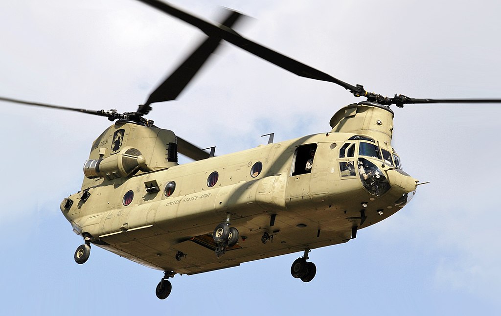
In contrast to the obvious upside of a huge multiplier, the downsides of using a Chinook Style helicopter are actually quite subtle. From a first glance, it is difficult to say why simply splitting the single-axis helicopter in half and placing the rotors side by side would cause flight times to take a huge hit, yet it does. The handicap from making a Chinook style can be summed up in 3 points.
Each point leads nicely to the next.
- The stability problem
- Extra weight
- Less stored power
Stability is the most glaring initial problem. First and foremost, creating a single helicopter with two rotor axes requires there to be some kind of connection between the two axes. Otherwise, the helicopter would become two separate (and dysfunctional) helicopters. Thus, I added a simple X-truss made of thin balsa to create the connection. Secondly, due to the nature of having both rotors on the top of the helicopter, the center of gravity of the entire system is not as ideal as the single-axis helicopter. In order to prevent the helicopter from swaying off course from the ideal vertical flight direction, some kind of resistance needed to be in place. The theory behind this is very similar to why arrows are tipped with feathers or rockets require fins. Thus, sheets of Mylar were coated over the middle X-truss to create Left/Right air resistance while not impacting the freedom of Up/Down motion. Finally, it is almost intuitive that symmetry must be preserved when creating the Chinook-style helicopter. If not for the reason of weight balance (perhaps your helicopter has asymmetrical geometries but the center of mass is still preserved), then it may be for the reason of torque balance! To make the helicopter flies straight and stable, the two rotors must be generating EQUAL amounts of lift force. Otherwise, one side accelerates faster than the other and the helicopter begins flying sideways. Assuming the two rotors are identical, difference in lift force is dependent solely on difference in rotor torque, which comes from the twisted rubber band. Subsequently, since there are two rotor axes now, there must also be two separate rubber bands. The factors that go into the amount of torque generated by the rubber band are the elasticity and length of the band, the number of twists, and the length it needs to span. The first two factors are independent of the geometry of the helicopter itself, but in order to keep the spanning length of the rubber band constant, the two axes must also have the same length. This justifies the necessity for design symmetry.
It should come as no surprise, but the addition of the X-truss and Mylar film in between the two rotor axes will serve to add more weight onto the helicopter. I have not even considered the addition of the extra spacer to keep the second rotor from hitting the ceiling as well. It should also come as no surprise that extra weight reduces flight time. From my experience, weight is by far the most significant factor of flight time. Consequently, I needed to find a way to shave off the extra weight that I just added to my helicopter so that it dropped back down to its original weight as a single-axis. Frankly there were not that many options. The most logical places to shave weight off were the spacers on top, but unfortunately the specifications on the spacers are outlined strictly by the Science Olympiad rulebook. With not much to shave off on the rotors without completely redesigning them, I had to shave length off of the two rotor axes. No big deal right? Well this all culminated to the biggest culprit in reduced flight time.
As mentioned earlier, the length of the rotor axes have an effect on the total rotational energy storable within the rubber bands. When the rotation axis is longer, it allows more room for the rubber bands to span across, and thus the band loop itself can be larger. The larger the rubber band loop, the more twists it can store without snapping. The principle is analogous to a spring. Even with the same elastic properties, a short spring will never be able to stretch as long as a longer spring without deforming. The longer spring stores more energy, just as the larger band loop will store more energy in the form of a higher number of winds. Looking back at my Chinook copter, the length of the two rotor axes now were even less than half the length of the original single-axis helicopter! Keep in mind, I chopped the original in half, then shaved an additional length off to make weight. This was a scary realization. The cold hard truth was that this Chinook-style helicopter just had no way of storing the same number of rotor turns as the original. And that is the tragedy of the Chinook variant.
Nonetheless, I ended up making the right choice going for the multiplier with the Chinook design. Many teams I observed at competitions that year came with a similar mindset and willingness to try something new. Despite the very quick development of a new kit in the market, I constructed my design prior to the existence of the kit. For that brief time window, I was truly innovating! I felt value return to this engineering event. Sure, my crude design ended up being no match for the perfectionist design of the kit-makers, but at least I was being original. Here’s the video of my best flight.