Sean's Engineering Portfolio
Introduction
This car is a voice-controlled car that takes in 4 commands. The command “GO” makes the car move forward for about three seconds. “GO GO” makes the car move forward for about five seconds. “Leeeeft” makes the car go left. “Turn Right Mon” makes the car go right. Why the odd commands? Stay tuned to find out. This entire project was an introductory exercise to signals and control using purposefully low-level hardware for the course EECS 16B. The motors were cheap motors without a servo port and inconsistent rotational speeds. The circuitry components were all basic op amps, resistors, capacitors, and a single mic board which could by calibrated to convert auditory cues to voltage signals. The point of this project was to use simple circuit components to create a more complex and useful system as well as to process the information outputted by this system using a TI-Launchpad CPU.
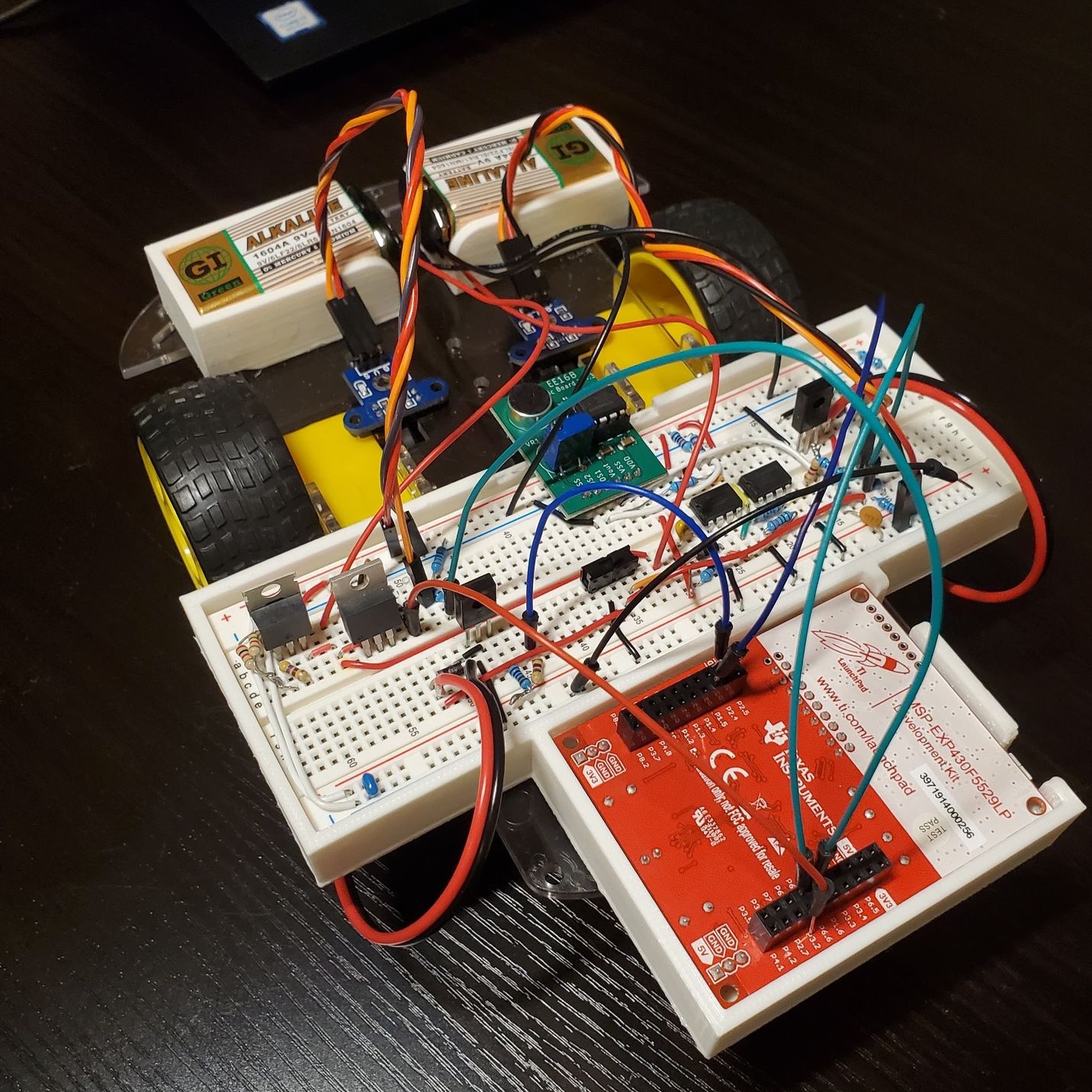
Hardware:
The hardware of this voice-controlled car mainly involves frequency filter circuits and voltage amplification using op amps. High and low pass filters are cascaded to form a bandpass filter that passes voltage signals between two cutoff frequencies. These voltage signals were generated by a calibrated mic board. Thus, my bandpass filter could “listen” for sounds within the vocal frequency range of the human voice. After amplifying signals within the desired frequency range using op amps, vocal cues were converted to electrical signals. Sixt33n now has ears.
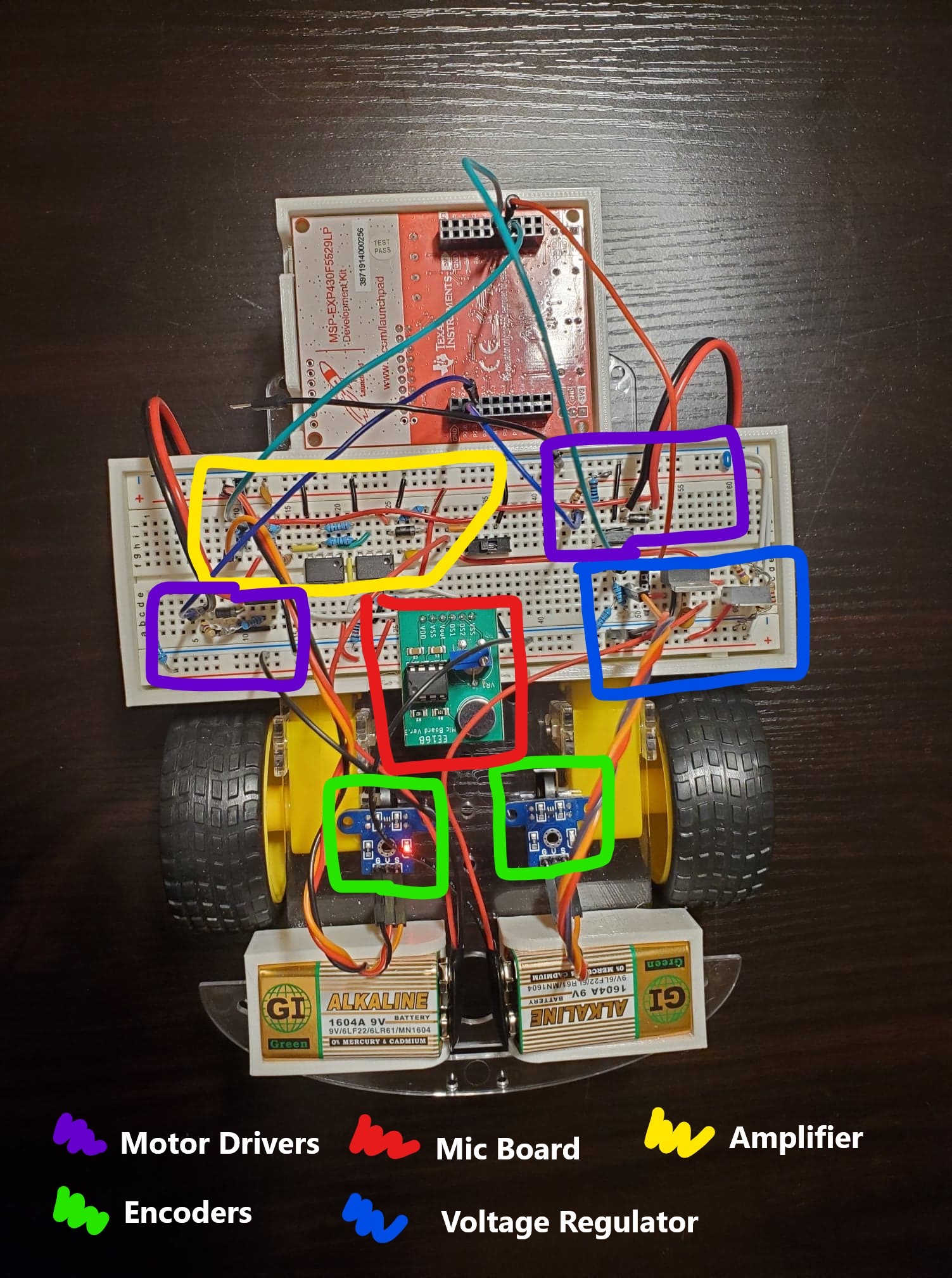
Controls:
The controls aspect of this project did not involve the mic or vocal recognition in any way yet was a continuation of front-end circuitry. By controls, I simply mean making the car go straight and turn right / left at a reasonable radius of curvature without overshooting. These are usually simple tasks for good motors, but we were using cheap servos with a separate encoder. I had to install my own encoders and photogates to read the rotational speed of these motors. After all the necessary circuits for motor control and tick reading were implemented on the breadboard, the real work began. First, I ran simple calibration tests that determined the base rotational speed of each motor given a range of voltages. Next, in the Launchpad, I implemented a closed-loop control scheme. In general, the scheme involves using the difference in wheel rotational speeds and multiplying this difference by a k-factor to determine the necessary adjustments in speed of each wheel upon the next discrete timestamp. To go straight, the car would adjust wheel rotational speeds with a target difference of 0 ticks/second. To turn right or left by a certain radius, the target difference in wheel speed was adjusted to a nonzero value based on some basic kinematic equations. Sixt33n is now all grown up and now knows how to drive.
PCA Signal Classification
Lastly, yet most importantly, the car needs to understand my commands. The car is programmed to listen over a two second interval. Within those two seconds I need to say something that is easy for the vehicle to identify. I chose to go with the aforementioned commands because of their syllable count and length. Each one created a sufficiently unique voltage signature which would be easy for my car to reliably classify. As for the actual classification algorithm, I won’t go deep into the linear algebra behind singular value decomposition (SVD) and principal component analysis (PCA). In simplest terms, the car takes in all the training vocal cues I give it and sums it all up into two nice parameters (two “principal components”). Whenever I speak to the car the car takes my words and maps it onto both principal components creating a coordinate (x, y). Then classification is simply a matter of finding the preprogrammed command closest in distance to the speech. Sixt33n is now able to think.
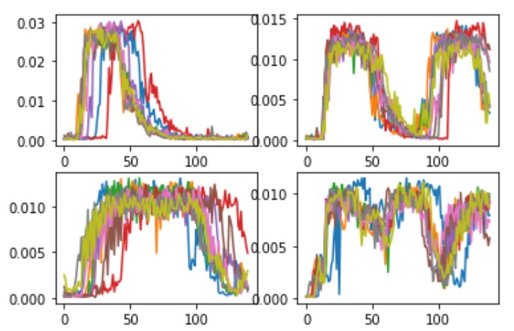
Sixt33n is alive! A simple car that can hear -> think -> drive. See the final closed-loop firmware.